Water cooled engines and absorbers both require a cold water supply. If you are using any type of water storage tank, or pump supply, review this information.
Note: For item-by-item details on the diagram, visit “Dynamometer Water Systems” Tech-Talk page.
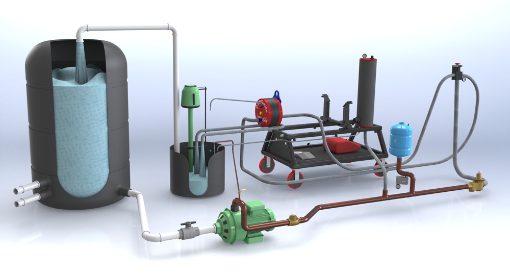
Bladder-tank storage (not shown) with pressure switch control of the pump is not actually required when using lawn-sprinkler type pumps (as shown above). However, if you decide to use pressurized storage, the pressure switch’s cut-in and cut-out points should be set fairly close together. This helps maintain a more constant pressure at the DYNOmite’s load valve. Consequently, the bladder tank should be quite large in capacity, to prevent short cycling of the pump.
A large in or above ground (un-pressurized) storage tank* (lager gray tank in image) provides an alternative to discharging hot waste water. If you are going to use a storage tank it must have a large enough volume (aka BTU capacity) for your anticipated power levels, run durations, and testing duty cycle. Loading 400 Hp will raise the temperature of 400 gallons of water by 150 degrees Fahrenheit in just 30 minutes. While some air cooling of the water occurs just sitting in the tank, for sustained testing you will need a water to air heat exchanger (e.g. a truck radiator and electric fan) to speed the storage tank cooling process.
CAUTION: Storage tank water can become contaminated with dangerous bacteria. Contact your plumber and building inspector for instructions on appropriate water treatments and health safeguards.
To read more about the treatment of storage tank water, you may want to visit sites like: www.tramfloc.com. Your local storage tank supplier may also have many useful suggestions. Some on-line suppliers of tanks include: www.plastic-mart.com and www.watertanks.com (these are just a couple of many).
*Plastic storage tanks listed below (with molded in tie down lugs and gallon markers) are available from US Plastics at 1-800-537-9724
Stock #10120550 gallon capacity 54” diameter x 67” height 130 pounds 10” fill well 2” female pipe thread bulkhead fitting (maximum temperature 140 degrees Fahrenheit)
Stock #10126 1050 gallon capacity 81” diameter x 57” height 205 pounds 10” fill well 2” female pipe thread bulkhead fitting (maximum temperature 140 degrees Fahrenheit)
Stock #10121 1300 gallon capacity 81” diameter x 67” height 250 pounds 22” removable manhole cover (18” diameter access) 2” female pipe thread bulkhead fitting
Notice that the pump in the above image has very-large diameter inlet and outlet fittings – in relationship to its electric-motor’s size. This is characteristic of high-volume pumps, as opposed to high-pressure pumps. Be especially careful to use large pipe and unrestrictive fittings to supply the pump. In the above image a (ball type) valve would be required in the white-plastic (PVC) supply line – to prevent the tank from self draining between test sessions..
Tip: Do not accept a high-pressure pump as a substitute for a high-volume pump. It will just cost you more (for a given flow capacity), will always require a regulator, and will self heat the water more at “idle”!
The small copper line and valve running from the pump discharge are to the sump tank is used to prevent pump overheating (between tests). It constantly circulates a little cooling water, anytime the pump is running. The valve allows setting this flow to just the trickle required to keep the pump-head cool.
The image shows a check valve (back-flow preventer) just after the pump discharge. This would really only be required when the supply is from a well or public water supply – which must be protected from possible back-flow of contaminated water from the dynamometer – most municipalities will require such protection by law
CAUTION: Always follow local plumbing codes when pluming your test cell.
The (optional) bladder tank (light blue tank in image) provides “anti-hammering” protection when the load valve suddenly closes. It also provides some extra (short duration) flow capacity during quick load-valve opening – helping control RPM during rapid throttle openings. The larger this tank, the longer it can supplement pump capacity during extreme demands.
Tip: Be sure to keep all plumping sizes large, right up to the load valve. Minimize the use of restrictive elbows, and use only “ball-type” valves (where required).
The large (very-high-flow) regulator, or pressure-reducing valve, (lower right in image) just before the load-valve control (upper right in image) should be used if the static pressure at the load valve (with valve closed) exceeds about 55 – 60 PSI. Too-high static pressure will cause valve binding and seal damage. High static pressure can also cause light-load control issues.
Tip: Be sure not to waste money on too small a load valve! An adequate size valve will usually need to be one (or two) pipe sizes larger than the pump’s discharge pipe run.
The real test of your water supply system is the dynamic (not static) pressure it can supply under maximum power-absorption demands. The way to test your dynamic pressure is to disconnect the hoses) from the absorber’s inlet fitting(s) and temporarily discharge them into a bucket. Next, fully open the load valve, while monitoring its pressure gauge. The lower-pressure observed, while the system is at full flow, is the dynamic pressure. This is the pressure reading that your tech-support person will want – when trouble shooting load-capacity issues.
Ideally, with an adequate pump and/or supply pipes, the dynamic pressure should not drop much below the static pressure! If the dynamic pressure is significantly less than (about) 40 PSI, consider a larger pump and/or larger inside-diameter supply piping. A significant drop, between the static and dynamic pressure, will reduce the absorber’s capacity and may make load control more erratic.
Tip: Never confuse the static (higher pressure) readings you get with the load-valve closed when asked for your dynamic pressure values. Dynamic pressure may only be measured with the hose off of the absorber and free flowing. The less dynamic pressure you have, the less power your absorber can handle!
MAX – Water-Brake Supply Volume – Animated look at how water volume and pressure effect engine loading (MAX narrated).
The absorber drain hose(s) must gravity discharge (no uphill hose runs allowed). Consequently, a sump tank and pump (as shown in image) is often required. The absorber’s vent hose(s) may run uphill, but must never be submerged at their outlet end.
CAUTION: The water in the sump tank will get hot during high-power testing. Submersible-motor type sump pumps are usually not rated for such temperatures, so a remote motor style (as shown in image) is recommended.
If the storage water gets too hot during extended high-power testing, a larger-capacity tank and/or extended cooling are required. The pair of white PVC pipes at the bottom of the storage tank (lower left in image) represent heat-exchanger inlet/outlet lines. These could go to an outdoor cooling loop and pump system (e.g. roof-mount radiators).
Tip: Lager-truck radiators and fans are one way to build a low-cost heat-exchanger system.